Build Your Own Low Cost CMSIS-DAP Debug Unit
With CMSIS DAP[1] firmware source code available under Apache 2.0 license and with easy to use USB middleware supplied by microcontroller vendors, its now super easy to build your own Debug Unit to flash and debug any ARM Cortex[2] based MCU.
Debug Unit PCB
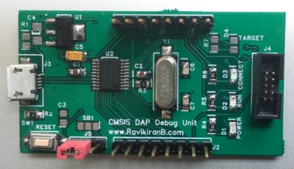
Since this project is open source, I decided to name this debug unit as OpenLink-V1 CMSIS-DAP.
To reduce the part procurement cost I have selected parts which are locally available in India either online or local electronic market, even if the part is not an optimum choice. For example, the debug unit is USB bus powered with current requirement of less than 100mA, but still the selected linear regulator or its equivalent, AMS1117-3.3 (SOT-223 package), has an output current rating of 1A. However this part is highly available locally and costs around Rs.9 per unit online.
Selected microcontroller is STM32F070F6P6[3] a low cost, low pin count (20 pin TSSOP package) easy to manually solder. This MCU is based on ARM Cortex-M0 CPU with USB 2.0 fullspeed interface, 32KB Flash, 6KB SRAM all sufficient for this project.
CMSIS-DAP firmware has two versions, version 1 uses USB HID interface to connect to Host PC and version 2 uses WinUSB as its host interface along with high-speed SWO trace streaming. With selected MCU, version 1 is the obvious choice. Advantage with USB HID interface is, it requires no driver installation on host PC.
Get Firmware and Hardware Design Files
Firmware source code, PCB design files and instructions are available on my GitHub
public repository:
https://github.com/rkprojects/openlink-v1-cmsis-dap↗
Validate the Debug Unit
Once you have assembled and flashed the debug unit, it needs be validated before use. ARM CMSIS-DAP firmware project provides a Validation[4] project based on Keil MDK5[5].
openlink-v1-cmsis-dap repository also includes this Validation project in its unconfigured form, it needs to be configured for your target board. How to do this is explained in its readme.txt file. Here I will show how to validate the debug unit with the NGX LPC4357 Xplorer++[6] target board.
Following instructions are to be carried out on Windows OS as Keil IDE is supported only on Windows.
- Go to openlink-v1-cmsis-dap/firmware/Validation/MDK5/ in the cloned repository directory.
- Open Validation.uvprojx project file in Keil uVision IDE.
- In Project Options -> Device tab: select target device as NXP LPC4357:Cortex-M4, you might have to download the NXP LPC4357 software pack if its not listed.
- For LPC4357, Keil needs post build step to correctly
generate flash signature.
In Project Options -> User tab: Add this After Build/Rebuild Step:
C:\Keil_v5\ARM\BIN\ElfDwT.exe !L BASEADDRESS(0x1A000000)
Update the path as per your installation. - Here ensure that you have plugged-in the debug unit's USB cable to the host and device is recognised as USB HID device in Device Manager. The debug unit is also connected to the target board's debug connector and target is powered on.
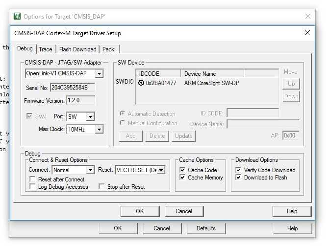
- In Project Options -> Debug tab: Select Use CMSIS-DAP Debugger and click Settings.
- In Debug settings select CMSIS-DAP JTAG/SWD Adaptor as OpenLink-V1 CMSIS-DAP
and Port as SW. Select the remaining settings as show in screenshot.
Project Options -> Debug tab -> Settings
- Click OK and close all dialog boxes, build and save the project.
- To validate, start debug session from the IDE.
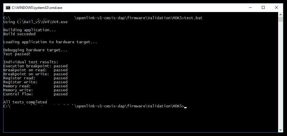
- Another way to validate: Open terminal in
openlink-v1-cmsis-dap/firmware/Validation/MDK5/ directory.
Edit test.bat to correctly point to UV4.exe and run test.bat
Output from test.bat
Debug Unit in Action
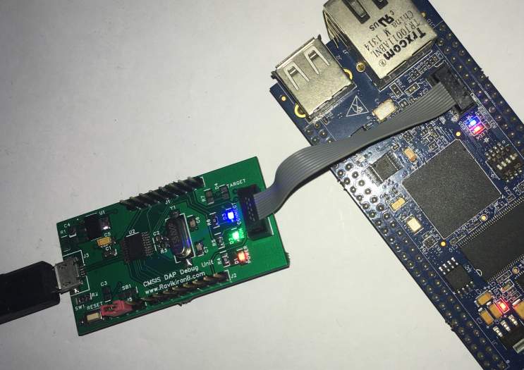
- Assuming you have mounted all the status LEDs on the debug unit, CONNECT and RUN LEDs reflects the status of debug session as the test progresses.
Debugging with GDB and OpenOCD
This section you can try out on either Windows or Linux OS. Since we are already in Windows lets continue with it.
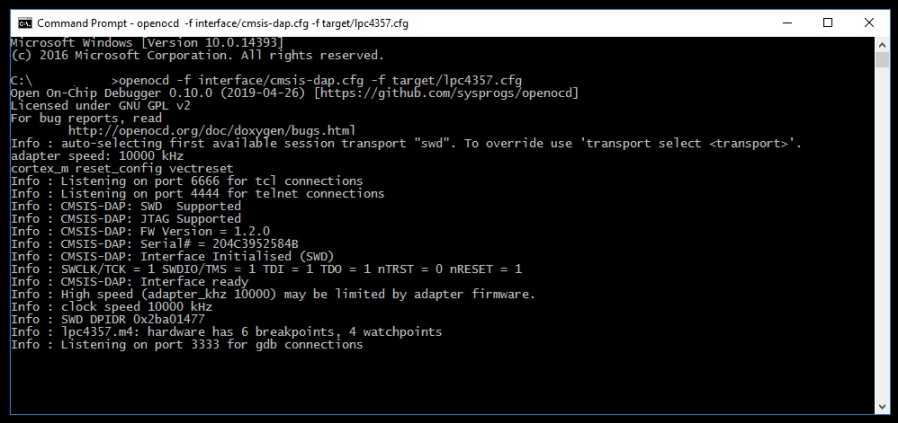
- Get the latest version of OpenOCD[7], which on this date
is version 0.10.0. Run OpenOCD with interface/cmsis-dap.cfg
and target/lpc4357.cfg.
By default the adaptor clock rate adaptor_khz is 500KHz which is slow, you can increase it
to 10000KHz.
After OpenOCD prepares the debug unit it will wait for GDB connection.Lets debug the same Validation project built with Keil but this time with GDB.
OpenOCD Session
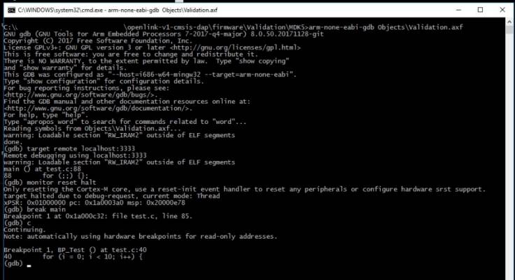
- Open terminal in openlink-v1-cmsis-dap/firmware/Validation/MDK5/ directory.
Start GDB with Validation.axf file. - Target board should already have the Validation test firmware, if not then run load command to update the flash.
- Now you can set breakpoints, step through the code and exit.
Sample GDB Session
- Notice that this time CONNECT and RUN status LEDs does not reflects any debug status, that's probably because OpenOCD doesn't make use of ID_DAP_HostStatus command.
Debugging with PyOCD
PyOCD[8] also supports CMSIS-DAP debug probes. To check whether our debug unit got detected run pyocd list in terminal, and to start its remote gdb server run pyocd gdbserver, now you can use gdb client to connect over localhost and debug, similar to OpenOCD.
PyOCD Session
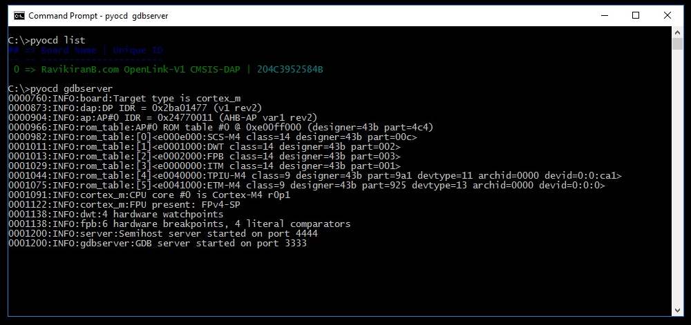
Notice that the detected target type is generic cortex-m processor, specific MCU package is required for flash programming and memory maps:
# Install MCU package:
> pyocd pack --install lpc4357

# Rerun gdbserver with target
> pyocd gdbserver --target lpc4357