Generic Communication with USB HID Device Class
USB Human Interface Device (HID) class offers the most easiest path to enable USB communication between an embedded device and a host computer without writing any device drivers. However we do have to write user space application if the device doesn't fall into any of the existing usages defined in HID class.
Before going further it is assumed that you have some working knowledge of USB 2.0 specification[1], you don't need to be an expert in USB protocols as the middleware libraries supplied by microcontroller vendors takes care of the all key parts of USB firmware implementation. If you have never read USB specification before then I would suggest reading USB in a Nutshell[2] before diving into the actual standard documents.
Human Interface Device Class
HID class device and host communicates using Control pipe (Endpoint 0), Interrupt IN pipe and an optional Interrupt OUT pipe. HID class specification[3] is applicable to low, full and high speed devices. As an example on maximum available bandwidth, at full speed with maximum 64 bytes of data payload, interrupt pipe can transfer 1216 bytes of useful data per frame[4]. Since interrupt pipes have bounded latency this kind frequent maximum bandwidth usage will choke the whole bus, this is the reason why different transfer types are defined in the specification. If the device data communication requirements can be met with two Interrupt pipes, we can go ahead with the HID class.
Before host can talk to the device it needs to know what is the usage or application of this device? How its data is organized? and What does the data actually measures?
Let's take a simple example to understand above questions: Let's say we have a System Power Control HID device, when a button is pressed on the device the host computer should enter sleep mode. All of this without writing any program on the host side.
For above events to happen the HID class driver must know:
- The connected HID device controls the System's Power state.
- There is a button on the device which when pressed, host has to enter sleep mode.
- If the device has many power control buttons then which one is for the sleep mode.
All this information is described in Report Descriptor. Once the class driver parses report descriptor it can interpret data coming on Interrupt pipes and pass it to corresponding application. Report descriptor is not returned along with Configuration descriptor while enumeration, only its length is included in the HID class descriptor, once the host knows that this device has a HID interface, HID class driver will issue GET_DESCRIPTOR request to the corresponding interface to get its report descriptor.
Report Descriptor
Report descriptor is described by sequence of items, together these items describe the data (also called report) that will flow on pipes. An item begins with a 1-byte prefix indicating the role of the item and its length, which can be short or long. Short item can have 0, 1, 2 or 4 bytes of data. Long item can have 255 bytes of data, long items are not defined in HID class specification.
Short items are of three types: Global, Local and Main. Each type is further divided into tags, let's look at some of them:
- Main item tags describes the actual data that will flow on pipes and collections of such data. Other tags of Global and Local item types add more properties to data described by Main item tags.
- Input item tag describes data sent on Interrupt IN pipe or control pipe, like button press events, sensor data, vendor defined custom data.
- Output item tag describes data send by host on Interrupt OUT pipe or control pipe, like changing LED state, driving motor, vendor defined custom data.
- Feature item tag describes data used to configure the device settings, like changing LED blink rate, setting motor speed. Feature data is sent on control pipe.
- Collection and End Collection item tag: All HID class devices must have at least one Application collection, class driver routes these collection data to appropriate applications. For example, a composite HID class device could have keyboard, mouse and power control buttons. Their corresponding items could be described with three application collections.
- Global item tags: These tags describes properties of all
Main item tags that follows until they are redefined.
- Usage Page describes top level category of this item like, Generic Desktop Controls, Game Controls, Telephone.
- Logical Minimum minimum integer value of a Main data item.
- Logical Maximum maximum integer value of a Main data item.
- Report Size size of Main data item in bits.
- Report Count Number such Main data items in the report.
- Local item tags: These tags describes properties of only the first
Main item tag that follows.
- Usage item tag further categorises the Usage Page Global item
tag. In the System Power Control HID device example above,
Usage Page is Generic Desktop Controls and within this page,
Usage is System Control.
Usage Page table and Usage tables are defined in HID Usage Tables document[5]
- Usage item tag further categorises the Usage Page Global item
tag. In the System Power Control HID device example above,
Usage Page is Generic Desktop Controls and within this page,
Usage is System Control.
Code snippet in Listing-1 shows the Report descriptor for System power control example, notice that on Interrupt IN pipe only one byte of report data is sent. Out of which only bit-0 has meaning.
| |
Generic Communication
HID class specification allows vendor defined Usage Page, which can be used to implement our own custom protocol with simplified report descriptor. HID class driver ignores vendor defined application collection and waits for vendor application to take control over the device. Lets take an example of ARM Cortex CMSIS DAP[6] Debugger unit, its firmware version V1 is implemented with HID class, we can use the USB HID Report Descriptor Viewer tool[11] to study its report descriptor, here is the output of the viewer from ULink2 debugger unit:
Usage Page(0xff00)      // Vendor defined page.
Usage(0x1)              // Vendor defined usage.
Collection(0x1)         // Application collection.
  Logical Minimum(0x0)
  Logical Maximum(0xff)
  Report Size(0x8)      // All data are byte sized.
  Report Count(0x40)    // Total input report size = 64 bytes.
  Usage(0x1)
  Input(0x2)            // Data is of variable type.
  Report Count(0x40)    // Total output report size = 64 bytes.
  Usage(0x1)
  Output(0x2)           // Data is of variable type.
  Report Count(0x1)     // Total feature report size  = 1 byte.
  Usage(0x1)
  Feature(0x2)          // Data is of variable type.
End Collection
If we control both device firmware and host application then there is no need to even parse the report descriptor. Lets use the above vendor defined report descriptor as a generic template and create another example to catch button press event and control LEDs over HID. Code snippet in Listing-2 shows the report descriptor used:
| |
For the above examples I am using NGX LPC4357 Xplorer++ Development Board[7]. LPC4357[8] micro controller is based on ARM Cortex-M4/M0 Cores, it is also supported with LPCOpen Software[9] library which includes the USB middleware stack.
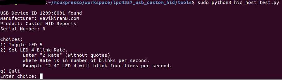
Now we need a host application to communicate with the USB device, easiest way is to go with PyUSB[10]. If you have the above development board you can try out these examples, they have been tested on Ubuntu 16.04.
Screenshot - Host Application
Get Source Code
Source code and instructions are available on GitHub public repository: https://github.com/rkprojects/generic-comm-usb-hid-examples↗
Conclusion
HID class specification is far more complex than what is covered here, wide varieties of usage pages and their usages for many human interface devices are defined in the standard documents. However if you want to build a simple generic communication model on top of USB with bounded latency then this much coverage is sufficient. Very low memory footprint can be achieved with HID class as it has simple endpoint configuration and with microcontrollers like LPC43xx with ROM based USB device stack, it further reduces memory requirements.
References
- USB 2.0 Specification↗
- USB in a NutShell↗
- USB HID Class 1.11 Specification↗
- Section 5.7.4 - Interrupt Transfer Bus Access Constraints, in USB 2.0 Specification↗
- HID Usage Tables Version 1.12↗
- ARM Cortex CMSIS-DAP↗
- NGX LPC4357 Xplorer++ Development Board↗
- NXP LPC4357 microcontroller↗
- LPCOpen Software for LPC43xx↗
- Python cross platform library for writing user space USB applications: PyUSB↗
- USB HID Report Descriptor Viewer↗